DALI-2 addressable module, 2 channels

The DALI-2 fully addressable 2-channel interface module allows up to 128 DALI endpoints to be connected to a Niko Home Control installation. Addressing and programming of the DALI devices is done from within the Niko Home Control programming software, and no prior DALI knowledge is required. Each of the DALI endpoints can be configured and controlled separately, without the need to use any other DALI software or interface. The module comes with a built-in power supply, so there is no need to use a dedicated DALI power supply for the DALI bus.
Support of DALI device types (control gear):
- DT0 (Fluorescent, lamp control gear)
- DT1 (Self-contained emergency, control gear)
- DT2 (Discharge HID, lamp control gear)
- DT3 (Low-voltage halogen, lamp control gear)
- DT4 (Incandescent lamp, dimmer)
- DT5 (Conversion to D.C. voltage, 1-10 V, 0-10 V converter)
- DT6 (LED lamp, control gear)
- DT7 (Switching, relay control gear)
- DT8 (Colour, control gear) is supported as of version 2.24 of Niko Home Control
The recommended solution for colour control and tunable white is DT8. However, colour control is also possible in DT6 mode if the DALI-2 addressable module is connected to a third-party DALI-2 LED driver that can be configured in a dual DT6 operating mode. In this set-up, two DALI-2 addresses are used: one to control light intensity and another to set the colour temperature. See guide.niko.eu for more details.
Product details


DALI-2 addressable module, 2 channels
The DALI-2 fully addressable 2-channel interface module allows up to 128 DALI endpoints to be connected to a Niko Home Control installation. Addressing and programming of the DALI devices is done from within the Niko Home Control programming software, and no prior DALI knowledge is required. Each of the DALI endpoints can be configured and controlled separately without the need to use any other DALI software or interface. The module comes with a built-in power supply, so there is no need to use a dedicated DALI power supply for the DALI bus.
Support of DALI device types (control gear):
- DT0 (Fluorescent, lamp control gear)
- DT1 (Self-contained emergency, control gear)
- DT2 (Discharge HID, lamp control gear)
- DT3 (Low-voltage halogen, lamp control gear)
- DT4 (Incandescent lamp, dimmer)
- DT5 (Conversion to D.C. voltage, 1 – 10V, 0 – 10V converter)
- DT6 (LED lamp, control gear)
- DT7 (Switching, relay control gear)
- DT8 (Colour, control gear) is supported as of version 2.24 of Niko Home Control
The recommended solution for colour control and tunable white is DT8. However, colour control is also possible in DT6 mode if the DALI-2 addressable module is connected to a third-party DALI-2 LED driver that can be configured in a dual DT6 operating mode. In this set-up, two DALI-2 addresses are used: one to control light intensity and another to set the colour temperature. See guide.niko.eu for more details.
Specification description
DALI-2 addressable module, 2 channels.
- Sliding contact to connect the module to the following module on the DIN rail
- Input voltage: 230 Vac ± 10 %, 50 Hz
- Maximum MCB rating: 16 A (limited by national installation rules)
- Output voltage: DALI
- Wire capacity
- 3 x 1.5 mm² of 2 x 2.5 mm² or 1 x 4 mm² wire per terminal
- Maximum standby consumption: 1,9 W
- DIN dimensions: 4U
- Dimensions (HxWxD): 90 x 70 x 66 mm
- Marking: CE
Related products
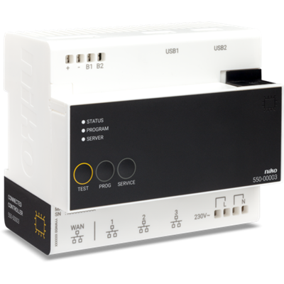
Connected controller for Niko Home Control II
The connected controller is the central module of every Niko Home Control installation for bus wiring. This module contains firmware that can only be programmed with the Niko Home Control programming software 2.1.1 or higher. It covers all basic functions on which a Niko Home Control installation is built. The basic functions include: • The intelligence directing the logic to the installation. Through the configuration software, the logic is saved locally on the controller. • The power supply module providing an input voltage of 26 V to the bus, the cabinet modules and the controls. Depending on the size of the installation, separate power supply modules can be added. • The connection to Niko Home Control IP devices such as touchscreens and external video units. A built-in router allows the user to connect up to 3 devices directly to the controller. With an extra switch, this number can be increased. • The connection to the internet. This enables the user to control the installation both indoors and outdoors (via mobile networks such as 3G, 4G, GPRS or Wi-Fi hotspot) using mobile devices (smartphones and tablets with iOS or Android). The module has a TEST button to verify the proper functioning and status of all other modules. Each installation must consist of one connected controller. After registration, your installation is connected, enabling control through the app via your smartphone and tablet, and you can enjoy the Niko services for upgrade or diagnosis of the installation.
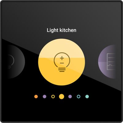
Digital black, connected customisable control screen, 24 V
Digital black is a customisable control screen for Niko Home Control with an extremely user-friendly interface with clear symbols. The screen is automatically activated when your hand comes near. That way, you can switch or dim your lights, set scenes, set ventilation modes, and adjust blinds and sunblinds to the desired position in one operation. In short, all possible Niko Home Control control types are available. As this Digital black 24 V variant is equipped with a temperature sensor and algorithm, it can be programmed as a zone-thermostat when linked to a Niko Home Control heating cooling module (550-00150) or switching module (550-00103 or 550-00106) programmed for electrical heating. Do you have an active connection with one of our heating partners? Then you can easily set the temperature with Digital black. When Digital black is used as a thermostat, you define the set points and week programs in the Niko Home app. With the Niko Home app you can choose which controls are displayed or where they are displayed on the screen, but also the way you navigate through your control screens. You can download this app for free in the App store or the Google Play store. Digital black can be easily mounted in any standard flush-mounting box using the familiar claw or screw fixing and is powered by a separate 24 Vdc supply (e.g. 340-00050). The screen communicates via your Wi-Fi network with the rest of your Niko Home Control system. You need an active internet connection to activate Digital black. This internet connection ensures that your Digital black and Niko Home Control installation are always up-to-date and have the most recent functionalities.
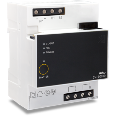
Power supply
The power supply, in combination with the connected controller, provides an extra input voltage of 26 V to the bus, modules and controls. An extra power supply is only necessary in installations for which the power of the built-in power supply of the connected controller is insufficient. Up to 2 extra power supplies can be connected to installations with a connected controller. The MASTER button is not used, as the built-in power supply of the connected controller is always the master. For more information on the required number of power supplies, you can consult the installation manual.