Step 2
Adapt intermediate switches
Identify the present connection diagram and mark the following wires with labels:
- Phase conductor supplying 230V
- Wires that lead to the lamp
The connection diagram in the example is an intermediate switching with three control points. For every additional control point in the switching there is always one extra intermediate switch. The intermediate switches are always in the middle, with a two-way switch on the two ends.
Warning: In reality, the switching can look different to what you see on the drawing. The wires leading to the lamp do not always go upwards. Also, the phase conductor and neutral conductor may be in a different colour. Therefore, use a multimeter to correctly identify the connection diagram.
Current connection diagram
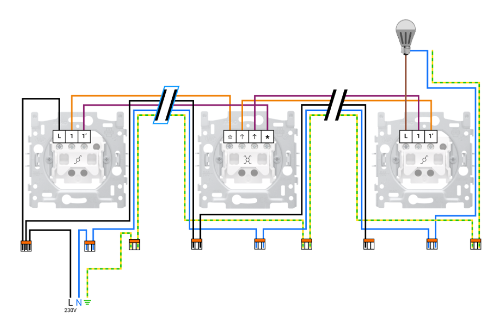

Warning: Your connection may look different, this example is only one of the options.
Niko Home Control connection diagram
Connect the connected double switch.
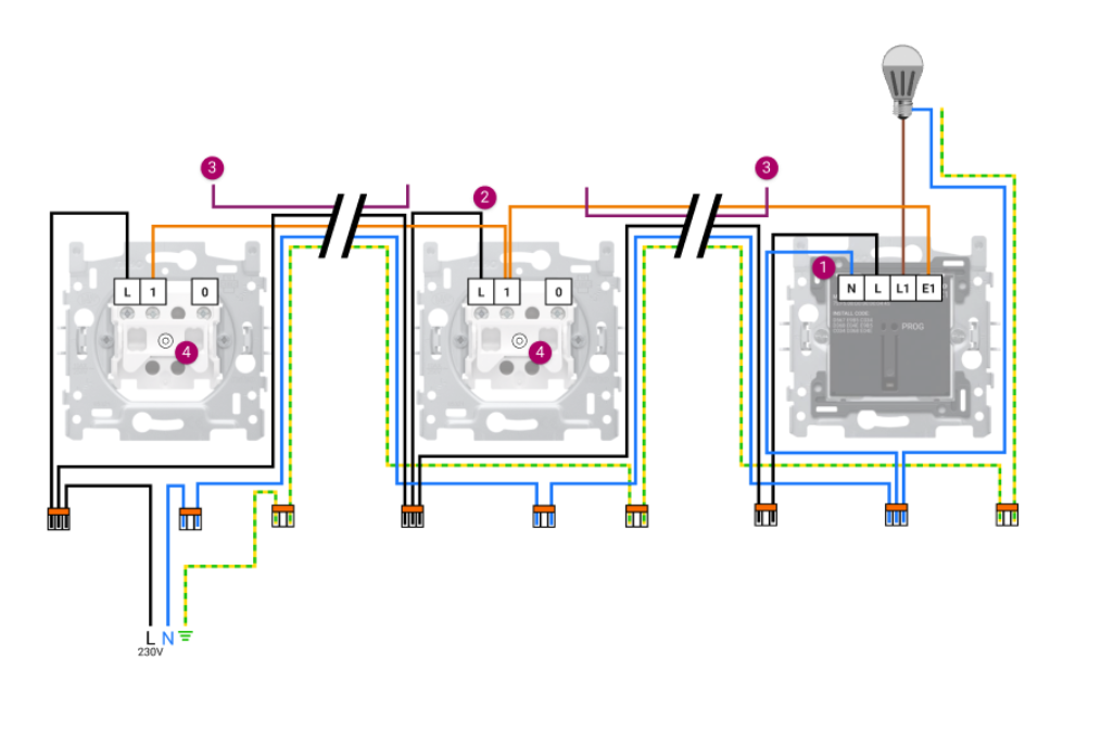
Warning: Always connect the connected switch directly to the lamp.
You need an extra wire❶ and a larger connection terminal❷, since you must connect the neutral conductor to the connected switch (you can also establish a connection via the N terminal). You also need an extra wire to connect the middle switch (traditional push button) to the L terminal ❸. When making connections with the push buttons, one of the switching wires will always no longer be used ❸. On the extension exit of the connected switch you connect traditional push buttons❺. Therefore you replace all switches.