Connection unit for multiple wall-mounted printed circuit board

The connection unit connects the installation to the multiple wall-mounted printed circuit board. The connection unit can be mounted into any position on the multiple wall-mounted printed circuit board. Note: Use a different set of claws.
Product details


Connection unit for multiple wall-mounted printed circuit boards
This connection unit forms the connection between the installation and multiple wall-mounted printed circuit boards. This unit can be mounted anywhere. To mount the connection unit, use the special set of claws.
Specification description
Connection unit for multiple wall-mounted printed circuit boards
Connection unit for multiple wall-mounted printed circuit board
A wall-mounted printed circuit board includes all the electrical and mechanical components required to connect one or several push buttons to the Niko Home Control installation. Niko offers horizontal, vertical, single or multiple printed circuit boards. Choose the type of printed circuit board depending on the number of action buttons required and on a horizontal or vertical assembly. The printed circuit board can be easily replaced by a larger one at a later stage if the need arises to expand the installation.
You need one connection unit for each multiple wall-mounted printed circuit board you wish to connect. Connection units are available separately. The connection unit includes a double plug-in connector, which allows you to connect the bus cable and establish a connection to the next control element. The connector has two contacts with two openings each.
Technical data:
- wall-mounted printed circuit board material: epoxy
- material thickness: 1 mm
- one double connector
Use a set of claws if no screw holes are provided in the flush-mounting box. Sets of claws for single and multiple wall-mounted printed circuit boards are available separately.
- Function: A wall-mounted printed circuit board includes all the electrical and mechanical components required to connect one or several push buttons to the Niko Home Control installation. Niko offers horizontal, vertical, single or multiple printed circuit boards. Choose the type of printed circuit board depending on the number of control buttons required and on a horizontal or vertical assembly. The printed circuit board can be easily replaced by a larger one at a later stage if the need arises to expand the installation. You need one connection unit for each multiple wall-mounted printed circuit board you wish to connect. Connection units are available separately. The connection unit includes a double plug-in connector, The connection unit includes a double plug-in connector, which allows you to connect the bus cable and establish a connection to the next control element. The connector has two contacts with two openings each.
- Wire connection
- double plug-in connector
- Wire capacity
- 2 x 0.5 to 1 mm² wire per terminal
- Fixing method
- to mount the connection unit, use the set of claws 450-00068.
- Dimensions (HxWxD): 50.7 x 42.9 mm
- Marking: CE
Accessories

Special set of claws
You can use this special set of claws to mount the connection unit for multiple wall-mounted circuit boards.
Specification description
Special set of claws
You can use this special set of claws to mount the connection unit for multiple wall-mounted circuit boards.
- Dimensions (HxWxD): 13 x 72.7 x 19 mm
- Marking: CE
Related products
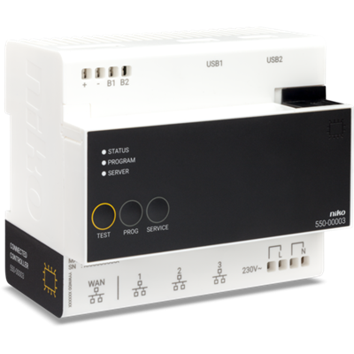
Connected controller for Niko Home Control II
The connected controller is the central module of every Niko Home Control installation for bus wiring. This module contains firmware that can only be programmed with the Niko Home Control programming software 2.1.1 or higher. It covers all basic functions on which a Niko Home Control installation is built. The basic functions include: • The intelligence directing the logic to the installation. Through the configuration software, the logic is saved locally on the controller. • The power supply module providing an input voltage of 26 V to the bus, the cabinet modules and the controls. Depending on the size of the installation, separate power supply modules can be added. • The connection to Niko Home Control IP devices such as touchscreens and external video units. A built-in router allows the user to connect up to 3 devices directly to the controller. With an extra switch, this number can be increased. • The connection to the internet. This enables the user to control the installation both indoors and outdoors (via mobile networks such as 3G, 4G, GPRS or Wi-Fi hotspot) using mobile devices (smartphones and tablets with iOS or Android). The module has a TEST button to verify the proper functioning and status of all other modules. Each installation must consist of one connected controller. After registration, your installation is connected, enabling control through the app via your smartphone and tablet, and you can enjoy the Niko services for upgrade or diagnosis of the installation.
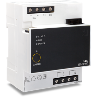
Power supply
The power supply, in combination with the connected controller, provides an extra input voltage of 26 V to the bus, modules and controls. An extra power supply is only necessary in installations for which the power of the built-in power supply of the connected controller is insufficient. Up to 2 extra power supplies can be connected to installations with a connected controller. The MASTER button is not used, as the built-in power supply of the connected controller is always the master. For more information on the required number of power supplies, you can consult the installation manual.

Rail coupler
This module is always mounted first on the left at the start of a new row of DIN rail modules that doesn't contain a connected controller or power supply. Interconnect the power supply and bus through the contacts at the top and bottom.